*** Project: Arduino & BMW K/I-Bus Interface ***
** Intro located here ***
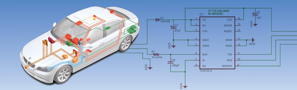
Below are the schematics for my Arduino & BMW I/K-Bus Interface that I created using Eagle PCB software – they are based on schematics from reslers’ interface as well as from Neiland, and with some help from ian332isport.
The TH3122 chip is an I/K-Bus Transceiver, which translates the +/- 12V K-Bus messages to/from +/- 5V TTL level serial messages.
The TTL level serial data can then be interfaced to either an Arduino/Teensy device, RS-232 (via MAX232 chip), or to USB (via CP2102 chip or a cheap commercial TTL to USB converter device).
Schematic: TH3122 to ARDUINO UNO R3
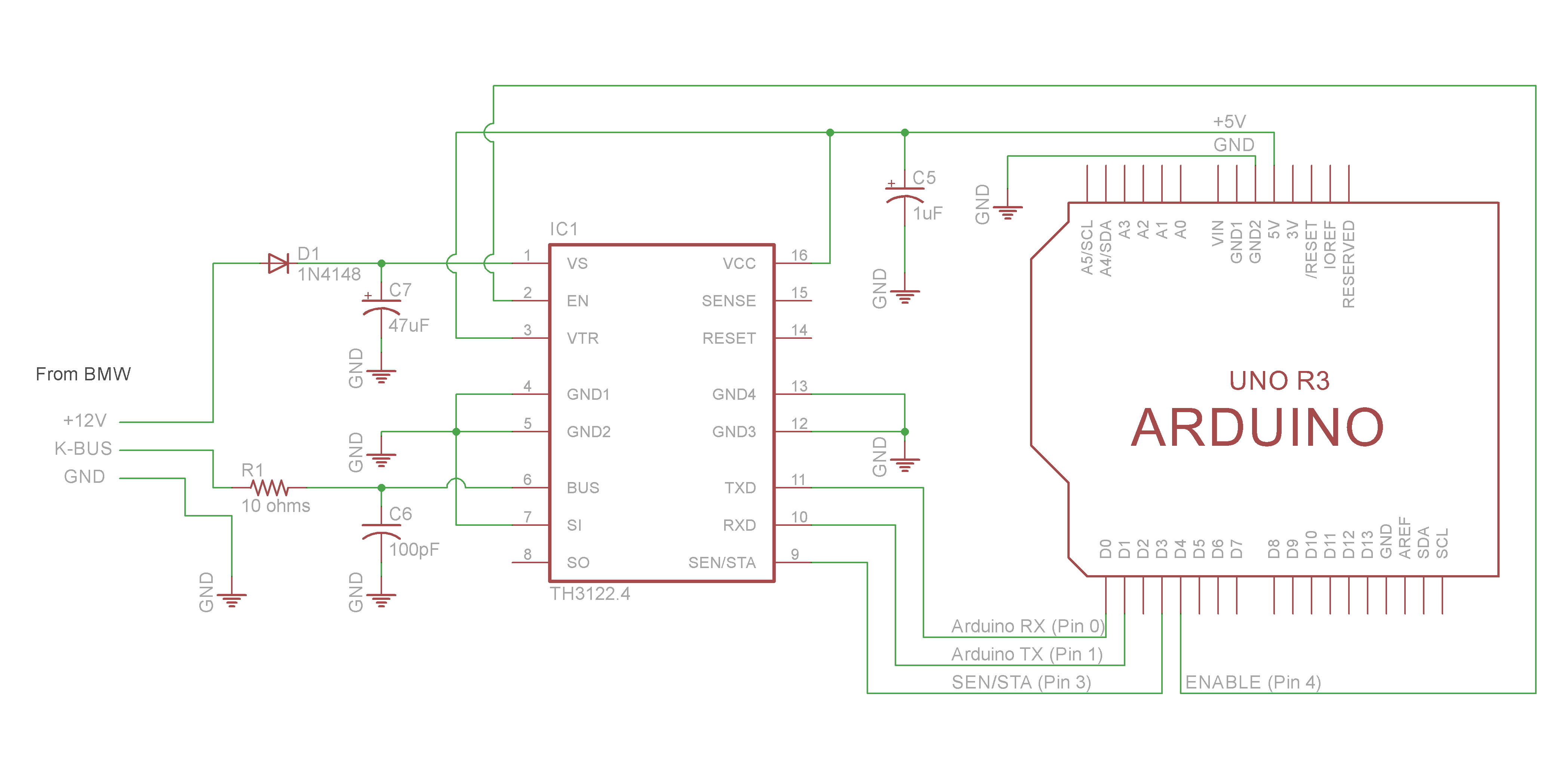
• K-Bus Line Input to TH3122
The BMW K-Bus wire passes through an RC filter and then connects to pin 6 (BUS) on TH3122.
The RC filter minimizes EMI on the BUS line, and is recommended per TH3122 datasheet.
The RC filter is a 10 ohm resistor and a 100pF non-polarized capacitor.
• Voltage Supply to TH3122
+12V supply voltage passes through a diode (D1), and connects to pin 1 (VS) which powers the TH3122.
The circuit has a 47uF capacitor on the +12V line to reduce short time voltage drops.
• Regulated Voltage from TH3122
VCC (Pin 16) provides the arduino with +5V; It is also connected to a 1uF capacitor (C5) to reduce short time voltage drops.
Capacitor C5 is suggested to be above 2uF in the TH3122 datasheet. I stuck with 1uF for flexibility (smaller variety of parts), due to the MAX232 datasheet specifying 1uF – for the RS232 interface.
Pin 2 (EN) enables the +5 Voltage regulator output on pin 16 (VCC).
We will use this in the arduino programming to shut down the arduino when there is no activity on the I/K-Bus after a certain time period. The TH3122 will automatically re-enable VCC (Pin 16) once it sees activity on the I/K-Bus – which will wake up our arduino.
• TTL Serial data to/from TH3122
Pin 11 (TX) is connected to the Arduino’s transmit pin.
Pin 10 (RX) is connected to the Arduino’s receive pin.
Pin 9 (SEN/STA) is connected to the Arduino’s digital input pin 3.
The SEN/STA signal stays High while there is data/activity on the K-Bus, and goes Low when there is no
activity. This is used in the Arduino programming to tell when it’s safe to send data onto the K-Bus.
• Misc
Pin 3 (VTR) is connected to VCC; It sets reset timing (See TH3122 Datasheet).
Pins 7 (SO) and 8 (SI) on the TH3122 can be used as a universal comparator.
We do not need this feature, so we ground pin 8 (SI), the comparator input.
Pins 14 (RESET) and 15 (SENSE) are not used for this project.
Pins 4, 5, 12, and 13 are all Grounds.
Optional debug schematic:
The Arduino programming includes optional debugging via Software Serial. This allows us to use a USB-TTL converter to monitor what the Arduino is seeing and doing. For the UNO R3 we use pins 7 (Rx) and 8 (Tx) for our Software Serial. Use your favorite serial monitoring software – I personally prefer PuTTy. See latest Arduino sketch code for more details (debug comments). Instructions on setting up the debug environment are available in the Operation and Testing section.
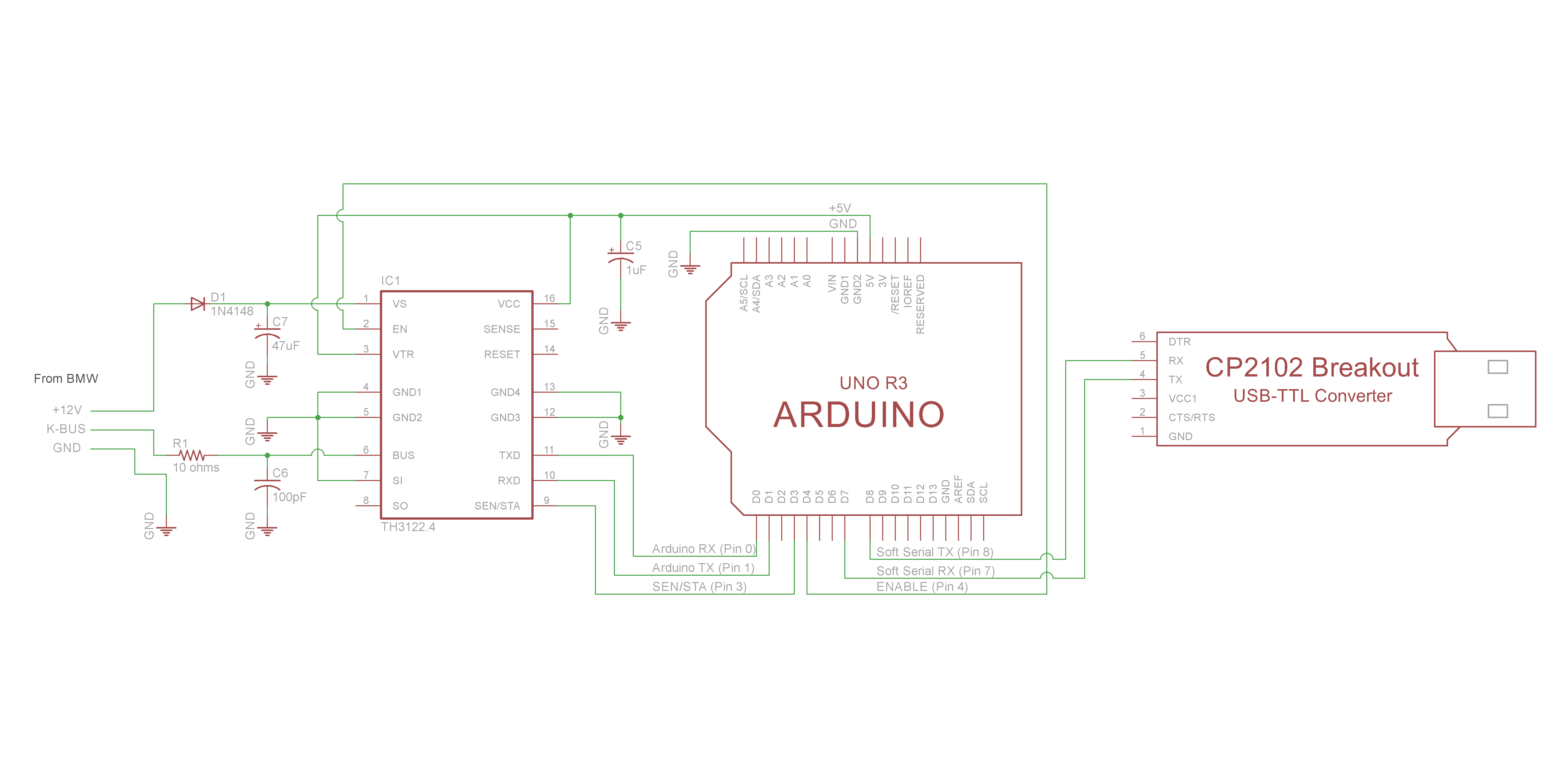
Schematic: TH3122 to USB TTL Converter (for NavCoder testing)
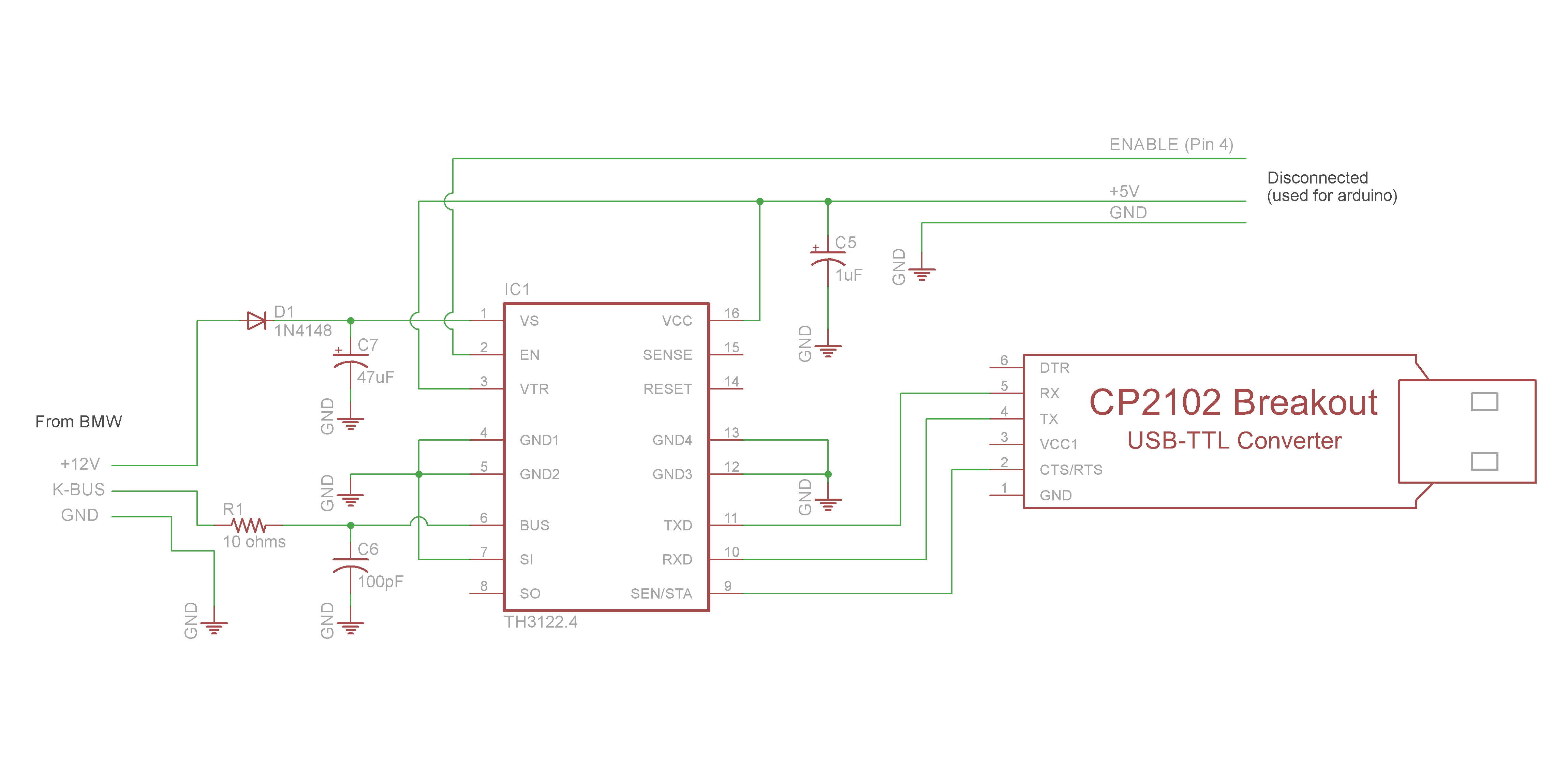
Description coming soon..
Last updated… Nov 19th, 2017
Schematic: TH3122 to RS-232 Serial
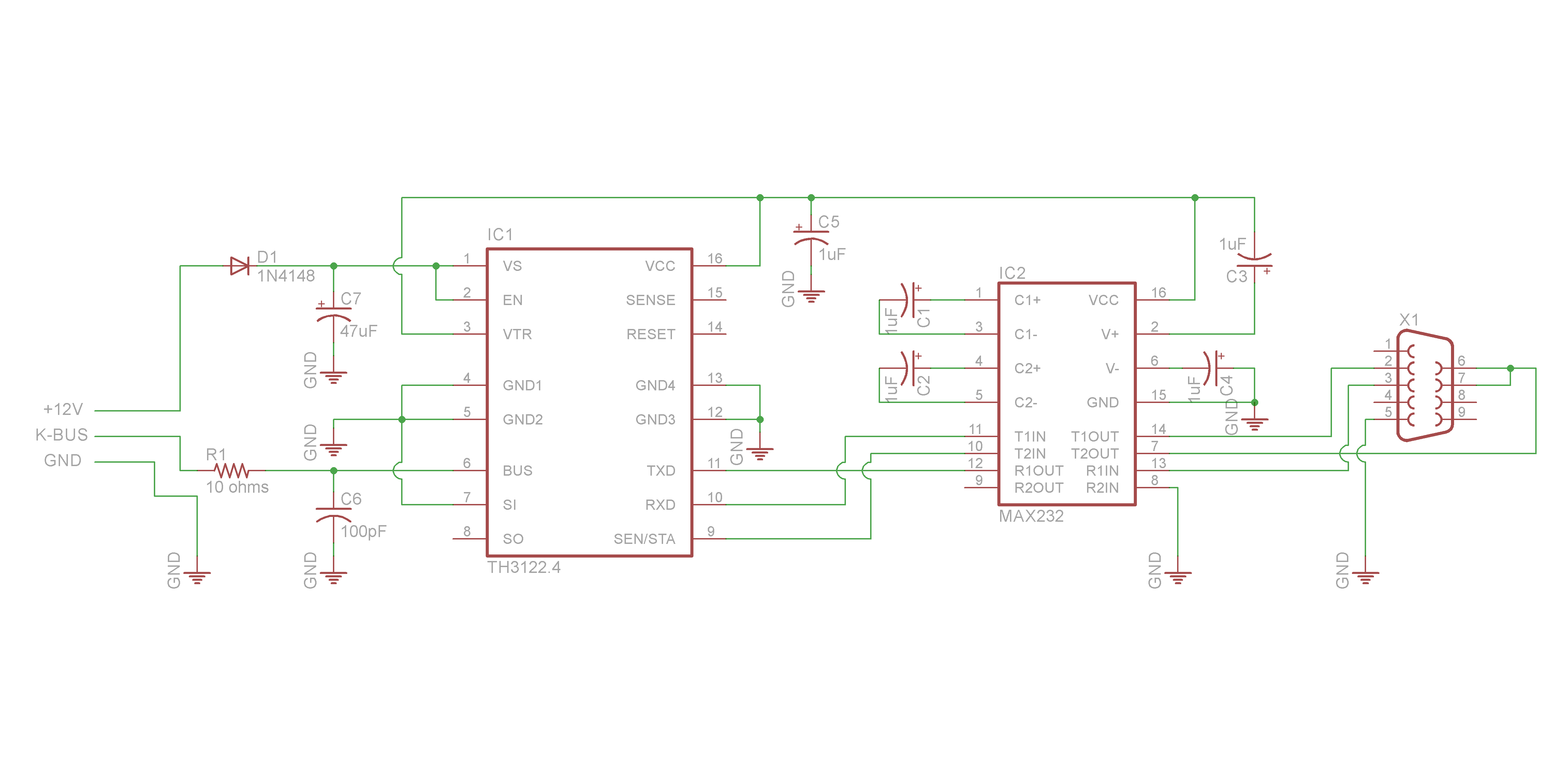
Description coming soon..
Last updated… Nov 19th, 2017
Project Continued:
• Intro
• Technical Details
• Schematic Description
• Resources & Downloads
• Programming
• Integration
• Messages