Curious-Ninja Logo
  • Home
  • Projects
    • Aviation
      • King Air Guides
    • BMW E46
      • K/I-Bus Interface
    • IT
      • UserLogos
  • Blog
  • About me
  • Contact
Curi0us Ninja Logo
19 Nov2017

Arduino & BMW I/K Bus Interface – Operation & Testing

November 19, 2017. Written by ninja. Posted in Blog, BMW E46, E46 K-bus, Projects

** DRAFT Nov 19th, 2017**

*** Project: Arduino & BMW K/I-Bus Interface ***
** Intro located here ***

Arduino Interface with debug:

Coming soon..

Designated section for info on:
– Setting up serial terminal software to monitor the Arduino in action
– Making customized changes to the Arduino sketch


USB-TTL Interface – NavCoder analysis:

Coming soon

Designated section for info on:
– Setting up NavCoder software to test and analyze messages live on the vehicle


  • Arduino & BMW K/I-Bus Interface

    • Project Table of Contents:
    • Intro
    • I/K-Bus Technical Details
    • Schematic Descriptions
    • Project Downloads
    • Arduino Programming
    • Vehicle Integration
    • Operation & Testing
    • I/B-Bus Messages

Continue Reading No Comments

11 Apr2016

Arduino & BMW I/K Bus Interface – Programming – v0.1.0 beta

April 11, 2016. Written by ninja. Posted in Blog, BMW E46, E46 K-bus, Projects

*** Project: Arduino & BMW K/I-Bus Interface ***
** Intro located here ***

Programming intro, and version summary is located: here.

The examples below are from version 0.1.0-beta. This version uses an I-Bus library to make things cleaner and simpler. All of the I/K-Bus communications is done using the library. 

All of the Arduino I/K-Bus code is available on my BitBucket page, as well as Google Drive (embedded below). 
Like I mentioned earlier, the coding was mostly done by ian332isport, and only slightly modified for projects’ my purposes.
Most of the code is fairly well commented, but I will provide a general description here anyway.

⚠ Module cannot be rendered as the requested content is not (longer) accessible. Contact the administrator to get access.

Code description:

Place the “Ibus” folder into your Arduino IDE libraries location. This is typically:

C:\Users\<username>\Documents\Arduino\libraries\

** In progress ** Last update: 11 APR 2016

• E46_KBus.ino


• auxFunctions.ino


I-bus Library:

• IbusGlobals.h

• IbusSerial.cpp

• IbusSerial.h

• RingBuffer.cpp

• RingBuffer.h


Project Continued:
• Intro
• Technical Details
• Schematic Description
• Resources & Downloads
• Programming
• Integration
• Messages  

Continue Reading No Comments

10 Apr2016

Arduino & BMW I/K Bus Interface – Programming – v0.0.1 alpha

April 10, 2016. Written by ninja. Posted in Blog, BMW E46, E46 K-bus, Projects

*** Project: Arduino & BMW K/I-Bus Interface ***
** Intro located here ***

The examples below are from version 0.0.1-alpha. This is an older version of the code, and requires and outdated Arduino IDE, as well as some modifications to the IDE core files. I suggest looking at the latest versions (which do not require core modifications and can use the latest Arduino IDE),  available: here.

All of the Arduino I/K-Bus code is available on my BitBucket page, as well as Google Drive (embedded below).
Like I mentioned earlier, the coding was mostly done by ian332isport, and only slightly modified for projects’ my purposes.
Most of the code is fairly well commented, but I will provide a general description here anyway.

There are two slight modifications that need to be made to the Arduino core files in order for this branch of code to work properly.
The files are “HardwareSerial.cpp” and “HardwareSerial.h”, located in the following directory:
“C:\Program Files (x86)\Arduino\hardware\arduino\cores\arduino”
This is due to the modification of function “Serial.peekn(n)”. Both of the modified files are included on my BitBucket page.

The Arduino IDE version that must be used is version 1.0.5 – this is due to modifying the two core files mentioned above.
I have not checked if these files have changed in any versions after 1.0.5.

⚠ Module cannot be rendered as the requested content is not (longer) accessible. Contact the administrator to get access.

Code description:

• E46_KBus.ino

This is the main program file (The one that must be opened with the Arduino IDE). The first section below is simply setting up variables we will use throughout the code.

E46_KBus.ino


// v0.0.1-alpha branch 
#include <SoftwareSerial.h>

// Setting up our variables
volatile boolean clearToSend = false;
boolean goodPacket; //boolean value set true if good IBUS message detected
int ibusEvent = 0; 
int EventID = 0; // Event number (for case select)
byte ibusByte[40]; // Byte array to store incoming messages.. Max message length per BMW design should be 32, plus the source and length bytes, makes a total of 34. Sticking to 40 for safety - don't want to overrun the array.
byte inByte[40];
byte source;
byte length;
byte destination;
byte databytes[36]; // Byte array to store message data bytes. ibusByte array of 40 - 4 for (Source, length, destination, checksumByte) = 36
byte checksumByte;
byte outgoingMsg[32];
int outgoingSize;
const int EN = 4; // HIGH enables Melexix TH3122 chip
const int senSta = 3; // SEN/STA output from Melexix TH3122 - Needs to be on pin 3 for interrupt 1 to work (on UNO/NANO - probably different on Mega)
const byte packetGap = 10; // Length of gap between messages we send
unsigned long currentTime;
unsigned long packetTimer;
unsigned long ibusSleepTimer;
// Debug - Used for sending debug messages to terminal window.
SoftwareSerial mySerial(7, 8); 
// 7 is Rx, 8 is Tx

// All these messages are either compared with incoming messages, or can be sent out onto the bus. Add or
// remove as required, but you need to make the necessary changes further down as well.
byte SEND_MESSAGE[32] = { 
  0xC8 , 0x00 , 0x80 , 0x23 , 0x42 , 0x32 };
byte KEY_IN [7] PROGMEM = { 
  0x44 , 0x05 , 0xBF , 0x74 , 0x04 , 0x00 , 0x8E }; // Ignition key in
byte KEY_OUT [7] PROGMEM = { 
  0x44 , 0x05 , 0xBF , 0x74 , 0x00 , 0xFF , 0x75 }; // Ignition key out
byte CD_STOP [7] PROGMEM = { 
  0x68 , 0x05 , 0x18 , 0x38 , 0x01 , 0x00 , 0x4C }; // CD Stop command
byte CD_PLAY [7] PROGMEM = { 
  0x68 , 0x05 , 0x18 , 0x38 , 0x03 , 0x00 , 0x4E }; // CD Play command
byte CD_PAUSE [7] PROGMEM = { 
  0x68 , 0x05 , 0x18 , 0x38 , 0x02 , 0x00 , 0x4F }; // CD Pause command
byte MFL_VOL_UP [6] PROGMEM = { 
  0x50 , 0x04 , 0x68 , 0x32, 0x11 , 0x1F }; // Steering wheel Volume Up
byte MFL_VOL_DOWN [6] PROGMEM = { 
  0x50 , 0x04 , 0x68 , 0x32, 0x10 , 0x1E }; // Steering wheel Volume Down
byte MFL_RT [5] PROGMEM = { 
  0x50 , 0x03 , 0xC8 , 0x01, 0x9A }; // Steering wheel R/T
byte DSP_VOL_UP_1 [6] PROGMEM = { 
  0x68 , 0x04 , 0x6A , 0x32, 0x11 , 0x25 }; // Rotary Volume Up 1 step
byte DSP_VOL_DOWN_1 [6] PROGMEM = { 
  0x68 , 0x04 , 0x6A , 0x32, 0x10 , 0x24 }; // Rotary Volume Down 1 step
byte DSP_SRCE_CD [6] PROGMEM = { 
  0x68 , 0x04 , 0x6A , 0x36, 0xA0 , 0x90 }; // DSP Source = CD

The section below is the setup and the main loop functions. The main loop runs millions of times per second – it first checks if the I/K-Bus has been idle for over 60 seconds in order to put the TH3122 IC into sleep mode, and shutdown the Arduino. The TH3122 will wake up automatically when it receives K-Bus voltage once again. The main loop then sends any messages that are awaiting in the circular buffer. And finally, the loop reads the serial buffer and passes the bytes to the readIbus() function.

void setup()
{
  Serial.begin(9600, SERIAL_8E1); // Set hardware serial for 9600 baud, Even parity and one stop bit
  mySerial.begin(9600); // Set debug serial speed
  mySerial.println(F("--IBUS reader--"));
  pinMode (EN, OUTPUT); // initialize pin.
  pinMode(senSta, INPUT); // Configure pin as input
  digitalWrite (EN, HIGH); // write pin high to enable TH3122.
  senStaTimer(); // Start contention timer
  packetTimer = currentTime;
  ibusSleepTimer = millis();
}
void loop()
{
  // Sleep Timer - Check if I-Bus has been inactive for 60 seconds
  if (millis() - ibusSleepTimer >= 60000) { 
    digitalWrite (EN, LOW); // Shutdown TH3122
  }
  
  // Check if we have packets waiting to be sent onto the I-bus in our circular Buffer.. and send them.
  // Inter packet gap timer on send
  if(clearToSend && cbAvailable() > 0 ) { // If clear to send, and messages waiting in circular buffer, send them.
  //if(cbAvailable() > 0 ) { // BENCH TESTING - NO clearToSend
    if (millis() - packetTimer >= packetGap) {
      sendIbusPacket();
      packetTimer = millis(); 
    }
  }
  
  if (Serial.available() >= 2) { // if 2 or more bytes in serial buffer, go and check for bus message
  readIbus();
  }
}

Continue Reading No Comments

08 Aug2015

Arduino & BMW I/K Bus Interface – Messages

August 8, 2015. Written by ninja. Posted in Blog, BMW E46, E46 K-bus, Projects

** DRAFT Aug. 8th, 2015 **

*** Project: Arduino & BMW K/I-Bus Interface ***
** Intro located here ***

Now that we’ve got our interface integrated to the car, we can either use NavCoder for message analysis, or our USB to TTL converter for debugging our Arduino interface coding.

As was discussed on the Technical Details page, the I/K-Bus packet structure looks like this:

1. Transmitter address (8 bit Source ID)
2. Length of data (number of following message bytes)
3. Receiver address (8 bit Destination ID)
4. Detailed description of message (maximum 32 bytes of data)
5. Summary of transmitted information (check sum)

The XOR checksum byte is used to check the integrity of the message. The receiver will compare that value with its own computation, and if not equal, will reject the packet.

 packet_structure

Below is an excel spreadsheet of various I/K-Bus messages and their descriptions.
I will eventually clean up and organize the spreadsheet into separate sections on this page for better readability. 

Multi-Function Steering Wheel (0x50):

Coming soon.

General Module V (0x3F):

Windows and Doors:

Lights:

Locks:

Coming soon.

Radio (0x68):

Coming soon.

Rain/Light Sensor (0xE8): 

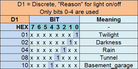
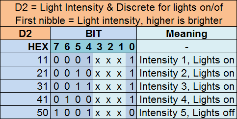
The RLS (Rain/Light Sensor, 0xE8) sends a message to the LCM (Light Control Module, D0) once every 10 seconds. The message contains:

• Ambient Light Intensity
• Lights on/off command
• Reason for lights on command

Examples of RLS messages:

  RLS messages

Databytes explained:

  RLS databytes

  RLS databytes

CD Player (0x18):

Coming soon.

Instrument Cluster (0x80):

Coming soon.

 Project Continued:
• Intro
• Technical Details
• Schematic Description
• Resources & Downloads
• Programming
• Integration
• Messages

Continue Reading 21 Comments

31 Jul2015

Arduino & BMW I/K Bus Interface – Schematic Descriptions

July 31, 2015. Written by ninja. Posted in Blog, BMW E46, E46 K-bus, Projects

*** Project: Arduino & BMW K/I-Bus Interface ***
** Intro located here ***

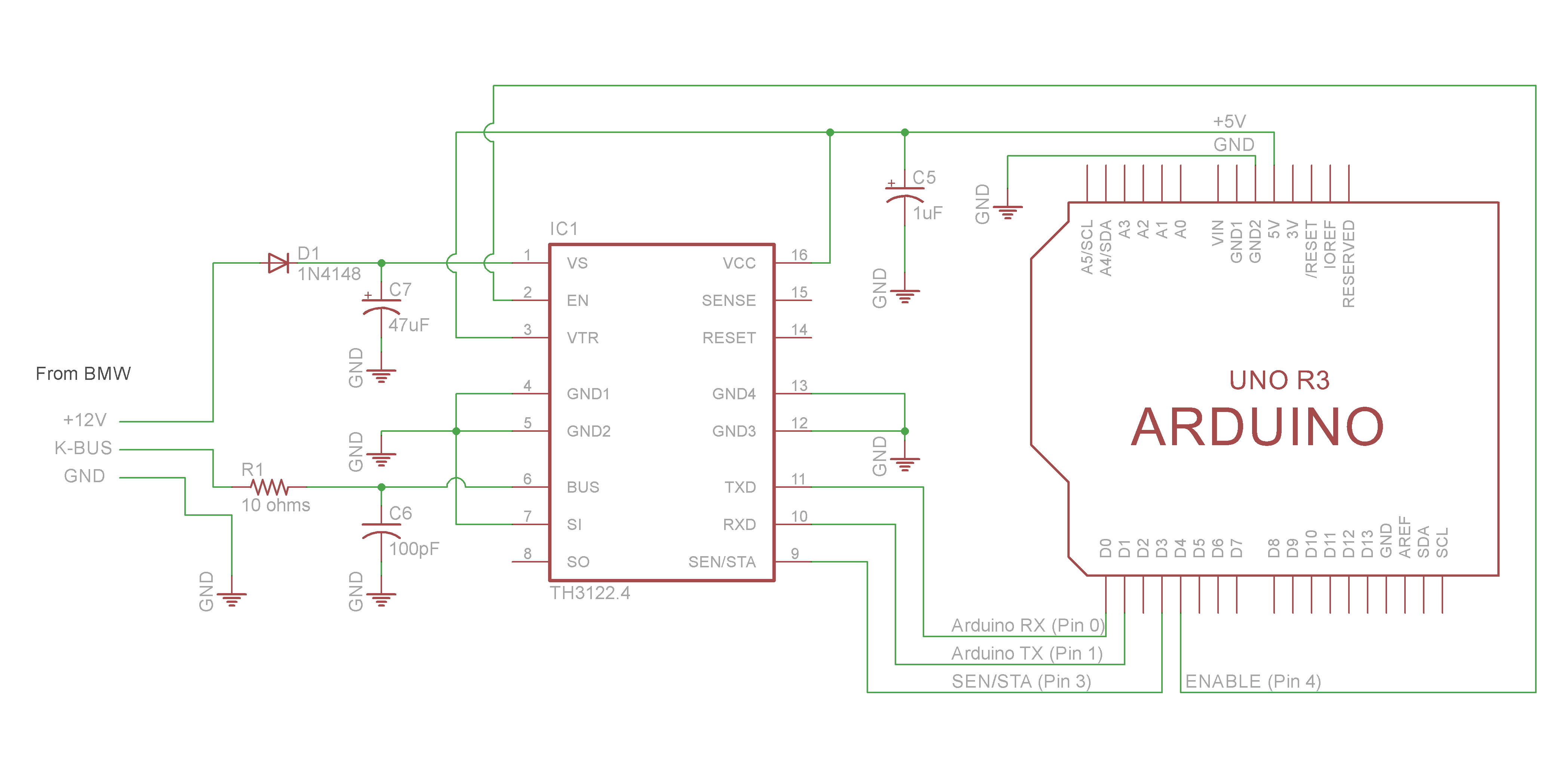
Below are the schematics for my Arduino & BMW I/K-Bus Interface that I created using Eagle PCB software – they are based on schematics from reslers’ interface as well as from Neiland, and with some help from ian332isport.

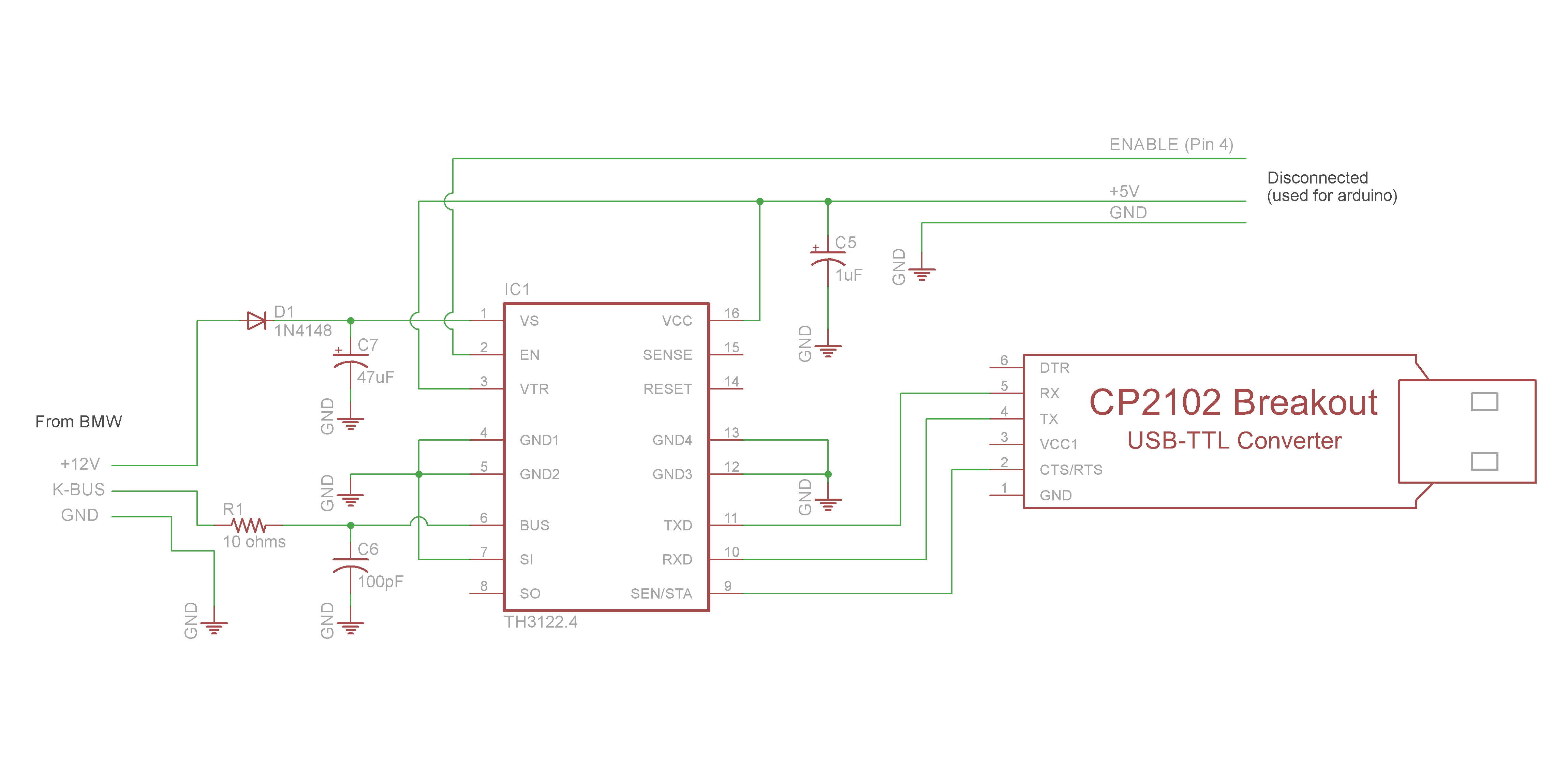
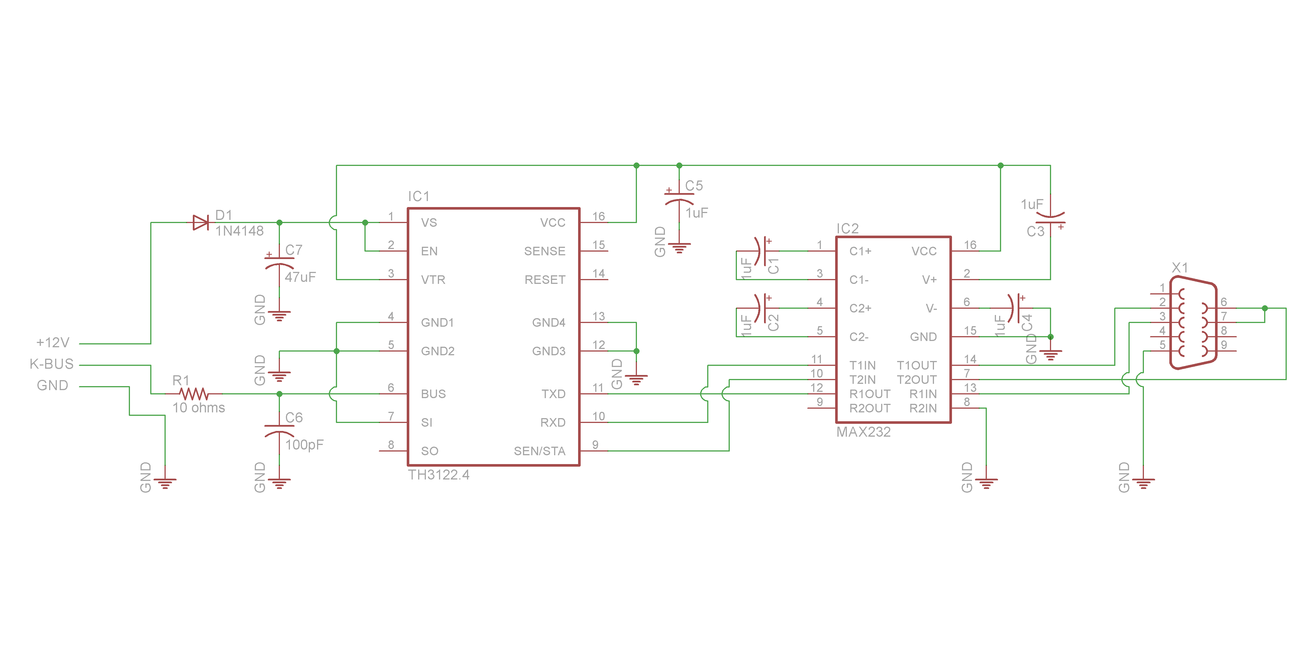
The TH3122 chip is an I/K-Bus Transceiver, which translates the +/- 12V K-Bus messages to/from +/- 5V TTL level serial messages.
The TTL level serial data can then be interfaced to either an Arduino/Teensy device, RS-232 (via MAX232 chip), or to USB (via CP2102 chip or a cheap commercial TTL to USB converter device).

Schematic:  TH3122 to ARDUINO UNO R3

Schematic TH3122 To ARDUINO

• K-Bus Line Input to TH3122
The BMW K-Bus wire passes through an RC filter and then connects to pin 6 (BUS) on TH3122.
The RC filter minimizes EMI on the BUS line, and is recommended per TH3122 datasheet.
The RC filter is a 10 ohm resistor and a 100pF non-polarized capacitor.

• Voltage Supply to TH3122
+12V supply voltage passes through a diode (D1), and connects to pin 1 (VS) which powers the TH3122.
The circuit has a 47uF capacitor on the +12V line to reduce short time voltage drops.

• Regulated Voltage from TH3122
VCC (Pin 16) provides the arduino with +5V; It is also connected to a 1uF capacitor (C5) to reduce short time voltage drops.
Capacitor C5 is suggested to be above 2uF in the TH3122 datasheet. I stuck with 1uF for flexibility (smaller variety of parts), due to the MAX232 datasheet specifying 1uF – for the RS232 interface.
Pin 2 (EN) enables the +5 Voltage regulator output on pin 16 (VCC).
We will use this in the arduino programming to shut down the arduino when there is no activity on the I/K-Bus after a certain time period. The TH3122 will automatically re-enable VCC (Pin 16) once it sees activity on the I/K-Bus – which will wake up our arduino.

• TTL Serial data to/from TH3122
Pin 11 (TX) is connected to the Arduino’s transmit pin.
Pin 10 (RX) is connected to the Arduino’s receive pin.
Pin 9 (SEN/STA) is connected to the Arduino’s digital input pin 3.
The SEN/STA signal stays High while there is data/activity on the K-Bus, and goes Low when there is no
activity. This is used in the Arduino programming to tell when it’s safe to send data onto the K-Bus.

• Misc
Pin 3 (VTR) is connected to VCC; It sets reset timing (See TH3122 Datasheet).
Pins 7 (SO) and 8 (SI) on the TH3122 can be used as a universal comparator.
We do not need this feature, so we ground pin 8 (SI), the comparator input.
Pins 14 (RESET) and 15 (SENSE) are not used for this project.
Pins 4, 5, 12, and 13 are all Grounds.

Optional debug schematic:

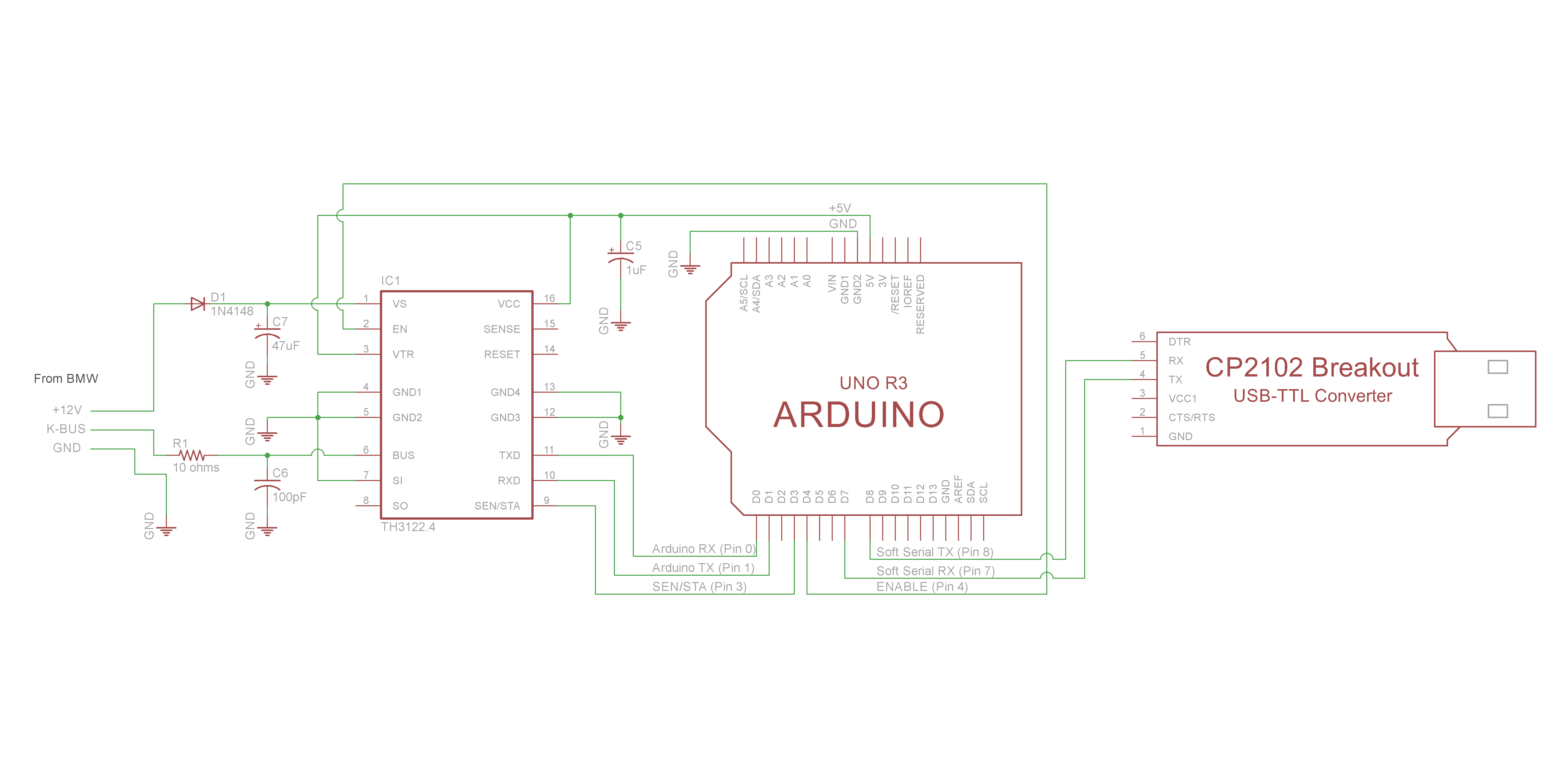
The Arduino programming includes optional debugging via Software Serial. This allows us to use a USB-TTL converter to monitor what the Arduino is seeing and doing. For the UNO R3 we use pins 7 (Rx) and 8 (Tx) for our Software Serial. Use your favorite serial monitoring software – I personally prefer PuTTy. See latest Arduino sketch code for more details (debug comments). Instructions on setting up the debug environment are available in the Operation and Testing section.

Schematic TH3122 To ARDUINO with Debug


Schematic: TH3122 to USB TTL Converter (for NavCoder testing)

Schematic TH3122 To USB TTL

Description coming soon.. 
Last updated… Nov 19th, 2017

Schematic: TH3122 to RS-232 Serial

Schematic TH3122 To RS232

Description coming soon.. 
Last updated… Nov 19th, 2017

 Project Continued:
• Intro
• Technical Details
• Schematic Description
• Resources & Downloads
• Programming
• Integration
• Messages

Continue Reading 7 Comments

  • 1
  • 2
NEW POSTS
  • King Air quickGuides December 29, 2018
  • Arduino & BMW I/K Bus Interface – Operation & Testing November 19, 2017
  • Arduino & BMW I/K Bus Interface – Programming – v0.1.0 beta April 11, 2016
  • Arduino & BMW I/K Bus Interface – Programming – v0.0.1 alpha April 10, 2016
  • UserLogos & Fast Dial August 10, 2015
ARCHIVES
  • December 2018
  • November 2017
  • April 2016
  • August 2015
  • July 2015
  • May 2015
TAGS
arduino bmw bmw e46 bmw i-bus bmw k-bus c++ chrome communications c plus plus details diy downloads e46 electronics fast dial firefox i-bus integration k-bus messages navcoder programming projects schematic serial speed dial technical testing userlogos wiring
Built with HTML5 and CSS3 - Curious.Ninja
  • Home
  • Projects
    • Aviation
      • King Air Guides
    • BMW E46
      • K/I-Bus Interface
    • IT
      • UserLogos
  • Blog
  • About me
  • Contact