*** Project: Arduino & BMW K/I-Bus Interface ***
This project was born because I chose to do a simple task the hard way. I have a hard-wired radar detector in my E46 BMW – an Escort Redline. The wiring kit includes an alert LED which flashes whenever the radar detector picks up a police radar band. The LED was the perfect brightness during day time, but was a ridiculously bright eye sore in the night time. Instead of simply using a photo-resistor to solve this issue, I decided I wanted to use the already available light sensor in the car.
The Rain/Light Sensor is mounted on on the top center of the windshield. It’s purpose is to:
1) Detect rain on the windshield to automatically turn on the wipers and set a proper wiper speed
2) Detect ambient lighting to control automatic headlight operation
It turns out the Rain/Light Sensor is connected to the cars’ internal serial communications bus. This is when I discovered the world of the BMW I/K-Bus.
The K-Bus is a standard bus protocol for automobile electronics. In other words, it is a way for devices within a car to communicate with each other. On the BMW, there are several devices on this bus. These include:
• Radio • MFW Steering wheel buttons • CD Changer • Light Control Module • etc
There are many possibilities when you are able to read and transmit on this bus.
Some examples of what’s possible by reading and writing from/to the I/K-Bus:
• Read misc sensor data (speed, temperatures, RLS, etc), and perform actions based on the data
• Control the radio unit, air conditioning, windshield wipers, etc
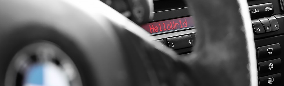
• Write text to the instrument cluster or the radio LCD displays
• Open/Close windows, sunroof, and trunk either manually or automatically based on any inputs
• Lock/Unlock doors either manually or automatically based on any inputs
• Control interior and exterior lighting either manually or automatically based on any inputs
• Control mirror and seat position (Including memory positions)
• Use inactive Multi-Function Steering wheel buttons for misc commands
The technical details of the bus can be found on the Technical Details page.
Planning the interface:
I decided to build my K-bus interface using an Arduino. For the record, I am not a software programmer. I’m only familiar with web based languages – PHP, HTML, CSS, etc. So i decided to take this opportunity to learn a bit of C++.
Before we get started, I should mention that there are several K-bus interfaces out there that convert the bus to RS-232 serial. This allows you to connect the I/K-bus directly to a PC/Laptop and then use software such as NavCoder to read the bus communications. The software even allows you to send your own custom HEX messages – if you know what you’re doing. This setup is VERY helpful in decoding the bus messages that you’re interested in. The most popular interface to use is the “Rolf Resler” interface, found here. In the future I will make a write-up on how to wire up the resler interface to the K-bus wiring below the radio, and use it with NavCoder for debugging purposes.
To be able to read and transmit on the K-bus via an Arduino we will need to build an interface circuit to convert the +/- 12V bus signals into something the Arduino can understand (+/- 5V TTL levels). After some research, I have found several online articles where people have used transceiver chips such as the MCP2004, MCP2025, or the TH8080. Some had event built their entire interface circuit from basic transistors, not using a chip at all.
I did quite a bit of research to be able to put this together – so keep in mind a lot of this info came from other users’ blogs and forums posts. I will list all my sources and give credit towards the bottom of this write-up.
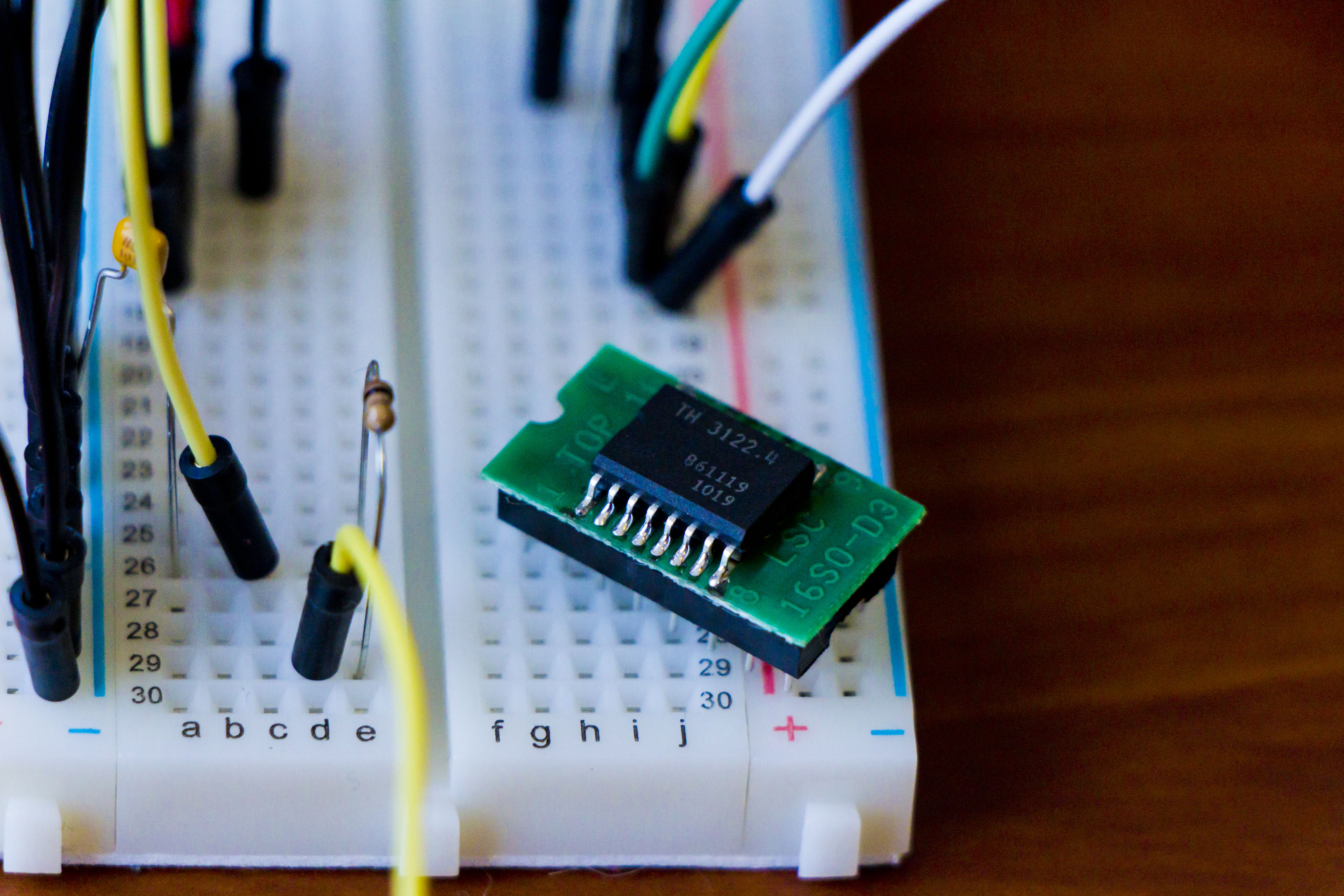
For my physical layer, I decided to go with the Melexis TH3122 transceiver IC. The chip connects to the the K-Bus, Ground, and the cars’ +12 volts and even outputs a regulated +5 volts to power other components (the Arduino!). It even has sleep/wake features, as well as a form of collision detection. The only drawback for the home hobbyist is that it only comes in a surface mount SOIC16 package. I was able to get a “SOIC to DIP” adaptor from digikey – more info on this in the Bill of Materials (BOM) below.
It turns out the TH3122 isn’t too readily available – digikey does not carry this IC. I was able to buy a couple from eBay.
Below is the schematic I created using Eagle PCB software – it is based on schematics from reslers’ interface as well as from Neiland, with some help from ian332isport.
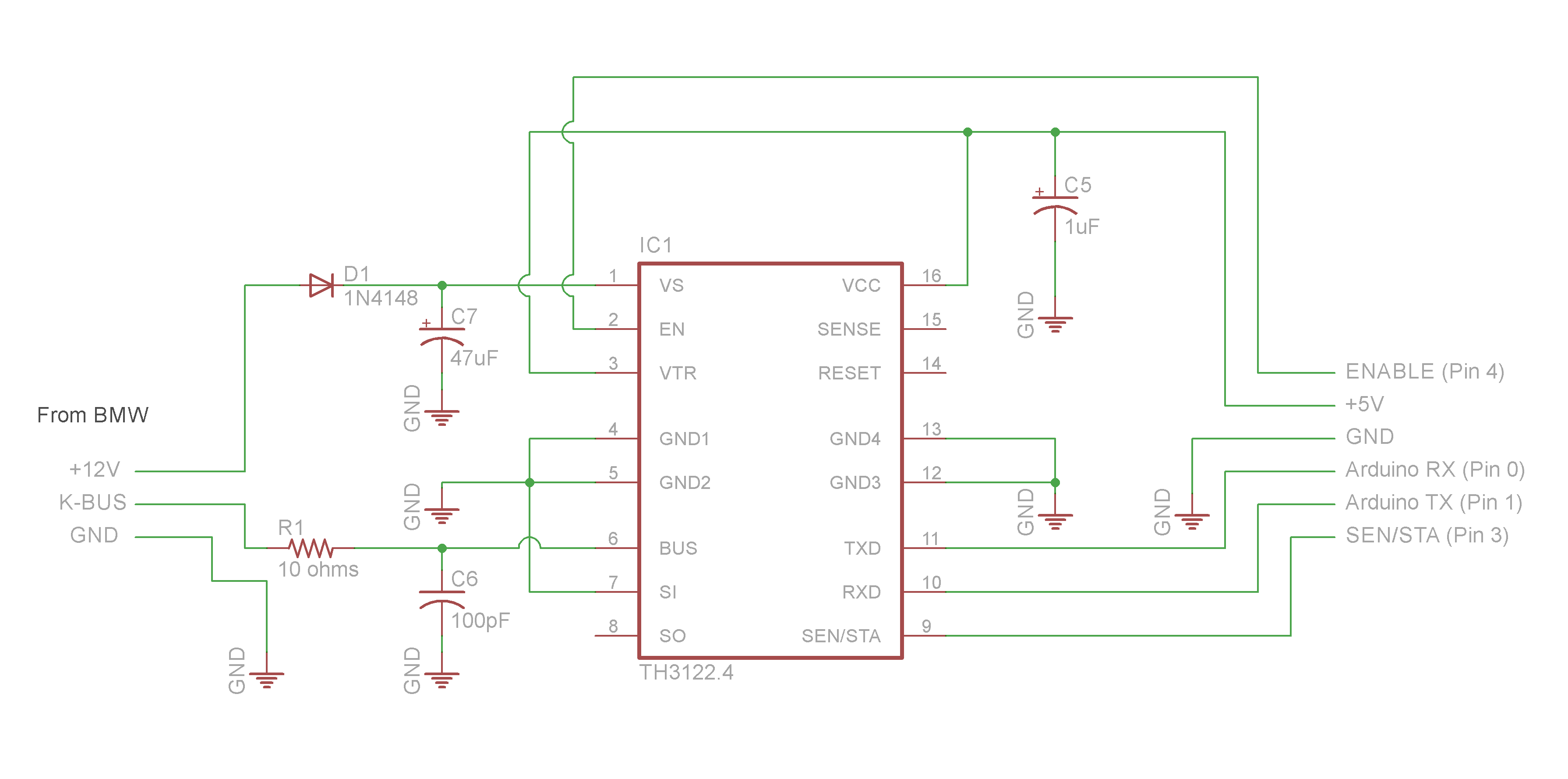
The description of this circuit can be found here.
Putting things together:
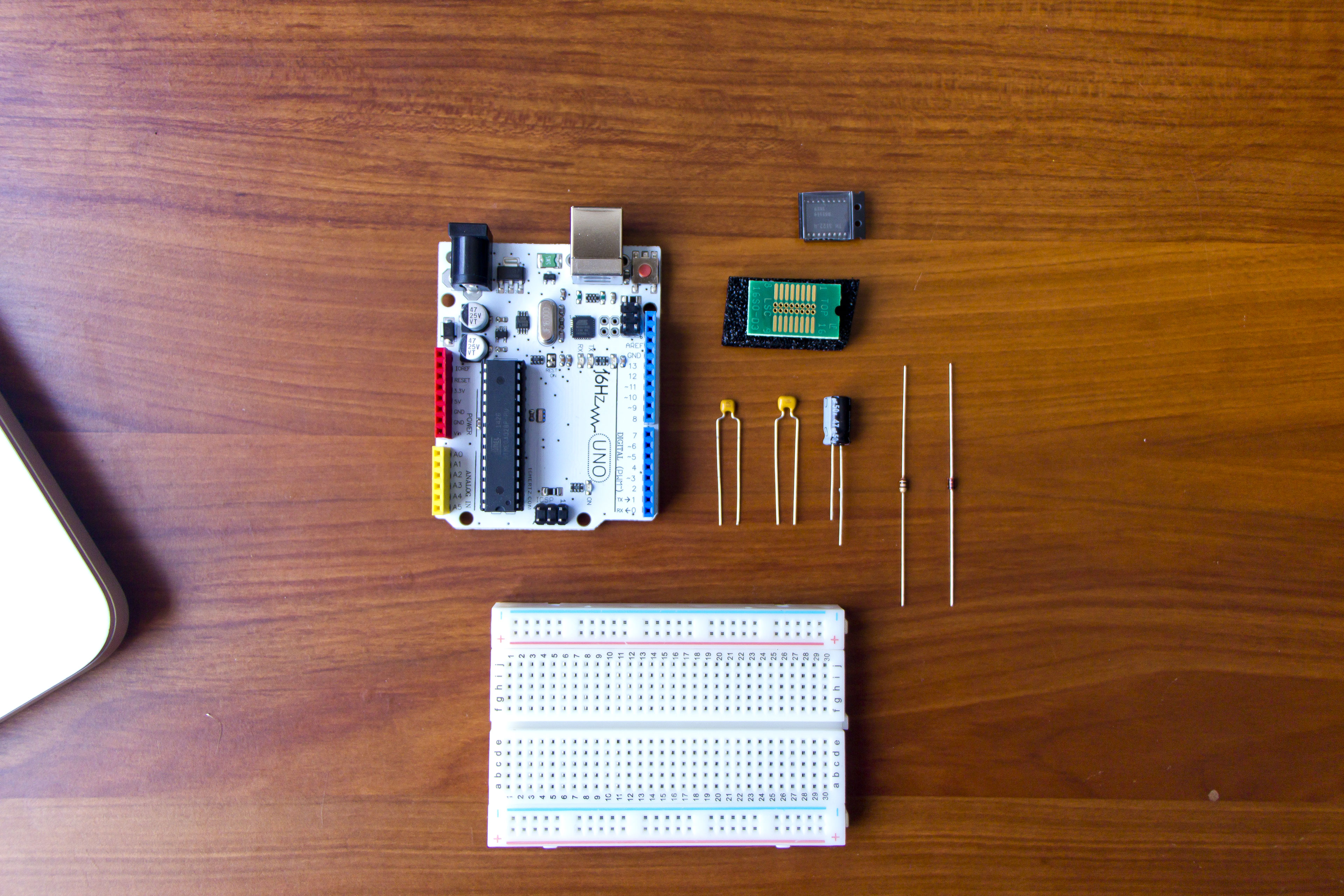
Assuming you already own an Arduino (I used an UNO R3 replica, from 16Hertz), the Bill of Materials (BOM) is:
• Diode 1N4148 • Resistor 10 ohms • Capacitors: 1uF 47uF 100pF • Melexis TH3122 IC • SOIC to 16DIP adaptor • Small breadboard • Breadboard wires • USB to TTL serial converter (optional but recommended)
Tools/Equipment:
• Soldering iron (for the TH3122 IC)
Links & details for Bill of Materials items are shown in the excel sheet below (Available in the resources & downloads section, “Physical Layer” folder).
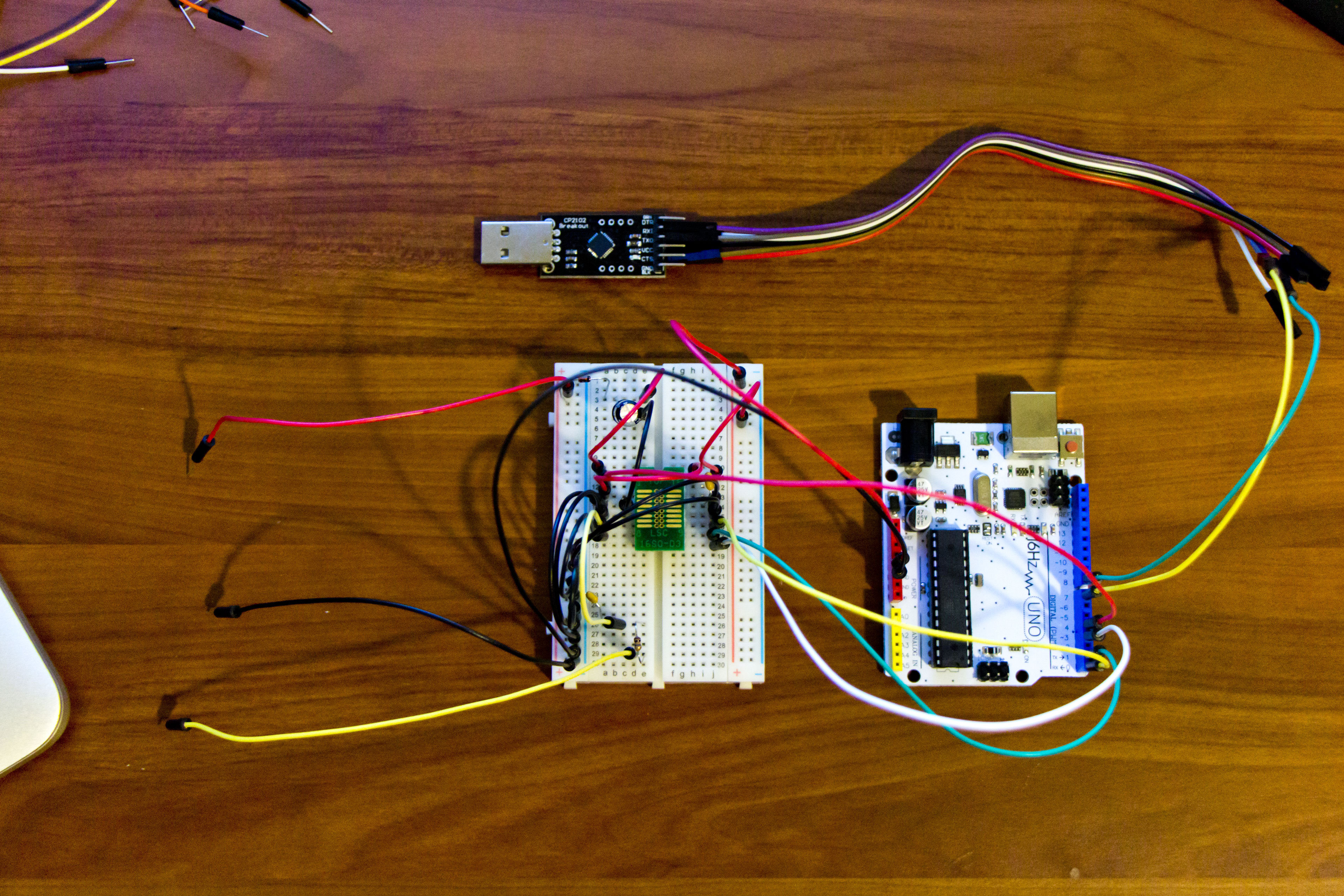
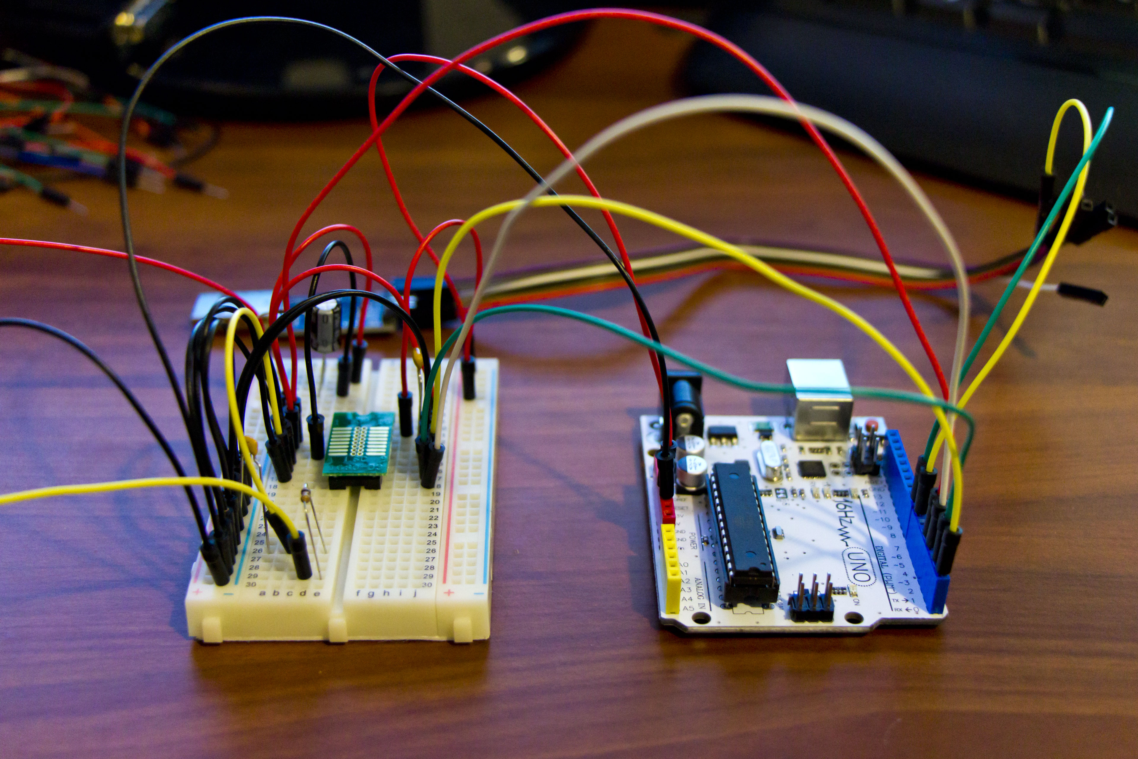
I soldered the TH3122 onto my SOIC to 16DIP adaptor, then assembled the Arduino breadboard according to my schematic.
The USB to TTL converter is very useful for debugging I/K-Bus messages using software serial. I am using pins 7 and 8 on the arduino. FYI, the signals must be crossed – Tx on arduino to Rx on the converter. Pin 7 on the arduino will be Rx and 8 is Tx. You can use any serial monitor software for debugging – I personally prefer PuTTy.
Photos for reference:

The next step is to program the Arduino..
Project Continued:
• Intro
• Technical Details
• Schematic Description
• Resources & Downloads
• Programming
• Integration
• Messages
Sources & Credit:
I’d like to make a shout-out to ian332isport, from the Arduino forums, for the much needed support with coding the Arduino.
He provided the base program I started with when working on this project.
My other sources and links for this project are located in the resources & downloads section.